High-quality metrology for quality control in the measuring room, production, incoming goods and development.
Gear Metering Pumps & Meter Mix Dispense Machines with highest accuracy for processing liquids and pastes.
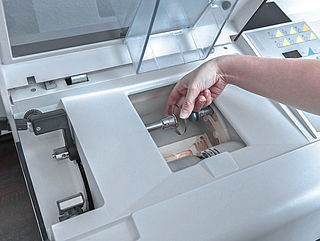
High-precision rotary stroke bearings for backlash-free linear and rotational movements for use in machine and device construction.


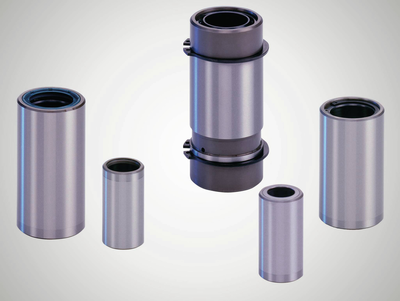
Ball-bearing guides for linear and rotational movements without play for use in all technical areas where reliability and precision are required.
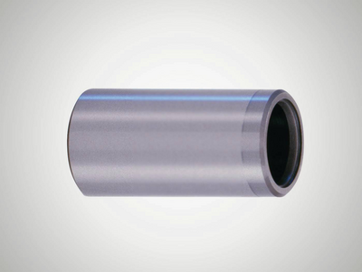
The guide diameter finely honed to ISO tolerance IT 3 guarantees the preload of the ball bearing guide in combination with shaft diameter ISO-h3.
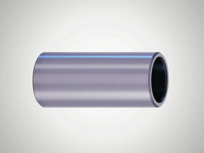
Universal, slim inner bevels on both sides.
Permanently installed thrust washers on both sides provide a safe travel limit for the ball cage.
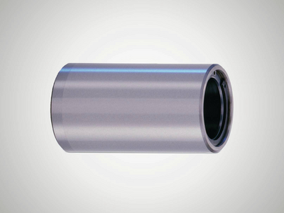
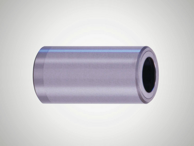
Permanently installed thrust washers on each side and sealing rings prevent impurities from getting into the ball bearing guide.
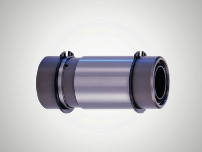
Extra sturdy model with scrapers on both sides which reliably prevent impurities from getting in, even in very dirty environments.
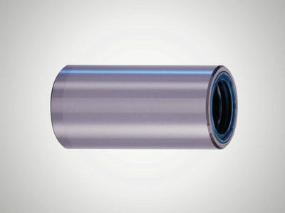
Universal, slim inner bevels on both sides, for use with ball cage from mini series N502.
Permanently installed thrust washers on both sides provide a safe travel limit for the ball cage from mini series N502.
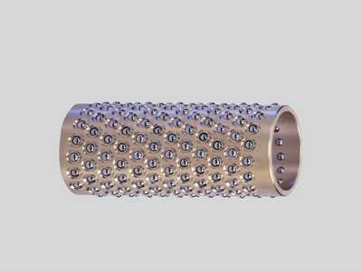
The balls can move easily without getting lost. The balls are arranged in such a way that they run smoothly and ensure a long service life of the ball bearing guide.
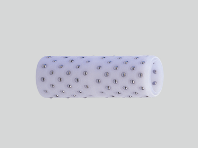
Excellent dry run properties and maximum smoothness, even at high accelerations thanks to the lightweight plastic.
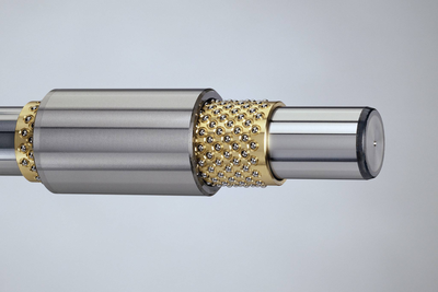
Versatile with balls arranged along a helical line, ideal for linear movements and rotational movements.
Smaller balls used with same shaft diameter compared to type N501. Reduced installation space thanks to guide bushes from the mini series.
High loading capacity thanks to large number of balls, reliable travel limit for the cage thanks to the securing ring.
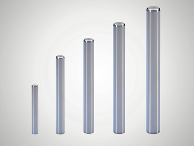
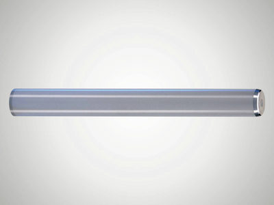
The finely-ground surface is ideal for high precision ball bearing guides, ensuring smooth running and a long service life of the ball bearing guide.
Preload is guaranteed when using with Mahr guide bushes and ball cages.
Inner thread on both sides, preload is guaranteed when using with Mahr guide bushes and ball cages.
Broader and more optimized range of uses.
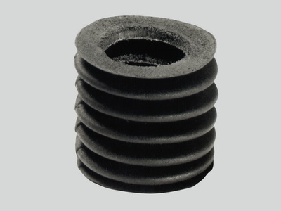
Protect open ball-bearing guides against dirt without compromising smooth movement.
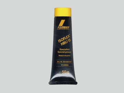
Lubrication for maximum performance and corrosion prevention.
Design and function
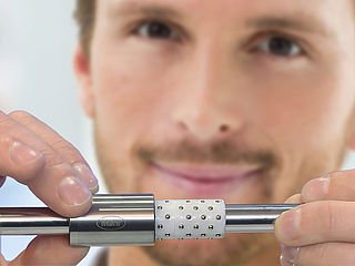
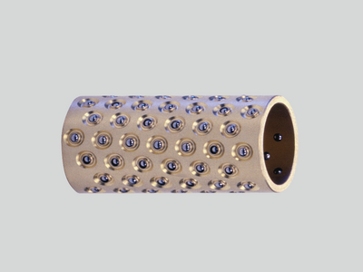
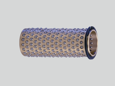
MarMotion rotary stroke bearings consist of the cylindrical components – guide bush and shaft – and steel balls as rolling elements, which are securely kept in a brass or plastic cage but remain easy to move.
The guide shaft, balls and guide bush are hardened and finely machined. The structure of the material is stabilized by careful heat treatment.
The preloaded balls roll slip-free between the guide bush and guide shaft. Linear movements, rotation and combined linear-rotary movements are possible. During a linear movement, the ball cage always travels 1/2 of the stroke path between the guide bush and guide shaft. The maximum length of the linear movement is determined by the overall lengths of the ball cage and guide bush.

Preload
The precisely adjusted preload is a prerequisite for the optimum and reliable function. It is specifically manufactured and defined by the manufacturing tolerances. The preload v is the difference between the dimension of two opposite balls, that are in contact with the shaft, and the inner diameter of the guide bush d1.
Size of the preload
For most applications, we recommend the preloads in the following table. The values are based on theoretical knowledge and practical experience.

Preload values
With these preload values, the rotary stroke bearing achieves a high level of rigidity combined with a very smooth movement. When ordering complete sets of rotary stroke bearings consisting of guide shaft, ball cage and guide bush, the components are already paired at the factory. This ensures a preload adjusted precisely at its optimum.
Due to the scattering range of the manufacturing tolerances (IT 3), the combination of guide bush, ball cage and guide shaft without proper pairing can result in unfavorable preloads deviating from the recommended values in the table. Rotary stroke bearings should therefore be ordered as complete sets, especially the rotary stroke bearings from the mini-range.
Meaning of the preload
The preload ensures that the MarMotion rotary stroke bearing is absolutely free of backlash. For applications subject to special conditions, the required preload can be specified when placing the order.
A small preload enables the very smooth running of the rotary stroke bearing, but the rigidity is limited. The load capacity and rigidity increase with a higher preload. A very high preload will result in more rolling friction.
A preload that is too high will result in rough and heavy running. The rotary stroke bearing can be overloaded by too high material stress on the surface. This is avoided by the narrow manufacturing tolerances of the rotary stroke bearing. Therefore, the guide bush must be handled with care to ensure that the diameter is not deformed during assembly.

Optimum preload
If a radial load with a force PR is applied to the rotary stroke bearing, then the axes of the guide bush and shaft a displaced by a value of δR. The permissible value δR is dependent on the preload v. The optimum preload has to be chosen based on the necessary loading capacity and rigidity.
The diagram shows the radial center offset of a rotary stroke bearing dependent on the preload and radial load. For a given radial force, the center offset with a small preload is relatively large: the rotary stroke bearing is soft. With a large preload, the center offset with the same radial force is significantly smaller: the rotary stroke bearing is hard.
Taking into account the Hertzian stress, the manufacturing tolerances and deformations of the components during installation and operation of the rotary stroke bearing, as well as the elasticity of the balls, the following value δR = 0.5 · v is used in the calculation basis as the maximum permissible center offset during operation. This condition is fulfilled for the specified "specific load ratings" C10. The demand for zero backlash is achieved.

Assignment of shaft and ball diameter
The ball diameter k has an influence on the amount of friction; a larger ball rolls more easily than a smaller one.
On the other hand, a large number of smaller balls results in a better damping capability against vibrations in comparison to a few large balls. For this reason, and because the installation space is often limited, preference is often given to the smaller ball. The required installation space for the ball-bearing guide is reduced by selecting guide bushes and ball cages from the mini-range with smaller balls.
The assignment of the shaft and ball diameter and the number of balls for the MarMotion rotary stroke bearings was determined by means of detailed research.
Coefficient of friction µ
MarMotion rotary stroke bearings run stick-slip-free.
The following coefficients of friction apply for radial loads:
high µ = 0.001-0.002<br/> average µ = 0.003-0.004
low µ = 0.005-0.008
The rolling friction of a rotary stroke bearing is determined by the internal load caused by the preload and the influence of external radial forces. If the radial loads are low, the proportion of friction caused by preload and cage predominates. Therefore, the coefficient of friction µ increases when the radial load is reduced. With a small radial load and the requirement for a very smooth movement, a low preload must therefore be used.