High-quality metrology for quality control in the measuring room, production, incoming goods and development.
Gear Metering Pumps & Meter Mix Dispense Machines with highest accuracy for processing liquids and pastes.
High-precision rotary stroke bearings for backlash-free linear and rotational movements for use in machine and device construction.


Ball-bearing guides for linear and rotational movements without play for use in all technical areas where reliability and precision are required.

The guide diameter finely honed to ISO tolerance IT 3 guarantees the preload of the ball bearing guide in combination with shaft diameter ISO-h3.

Universal, slim inner bevels on both sides.

Permanently installed thrust washers on both sides provide a safe travel limit for the ball cage.

Permanently installed thrust washers on each side and sealing rings prevent impurities from getting into the ball bearing guide.

Extra sturdy model with scrapers on both sides which reliably prevent impurities from getting in, even in very dirty environments.

Universal, slim inner bevels on both sides, for use with ball cage from mini series N502.

Permanently installed thrust washers on both sides provide a safe travel limit for the ball cage from mini series N502.

The balls can move easily without getting lost. The balls are arranged in such a way that they run smoothly and ensure a long service life of the ball bearing guide.

Excellent dry run properties and maximum smoothness, even at high accelerations thanks to the lightweight plastic.
Versatile with balls arranged along a helical line, ideal for linear movements and rotational movements.

Smaller balls used with same shaft diameter compared to type N501. Reduced installation space thanks to guide bushes from the mini series.

High loading capacity thanks to large number of balls, reliable travel limit for the cage thanks to the securing ring.

The finely-ground surface is ideal for high precision ball bearing guides, ensuring smooth running and a long service life of the ball bearing guide.

Preload is guaranteed when using with Mahr guide bushes and ball cages.
Inner thread on both sides, preload is guaranteed when using with Mahr guide bushes and ball cages.

Broader and more optimized range of uses.
Protect open ball-bearing guides against dirt without compromising smooth movement.

Lubrication for maximum performance and corrosion prevention.
Forms of the static radial load
Uniform constant radial load
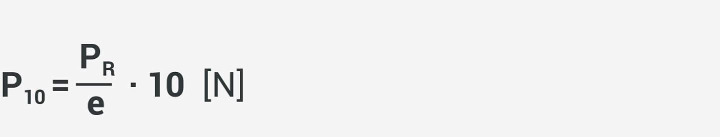
The radial force proportion of each 10 mm long ball zone equals:
The expected parallel displacement of the shaft equals:
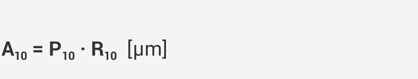
P10 in N, R10 in µm/N from the table Specific load rating C10 and suspension R10
Moment caused by radial force
The end zones of the ball contact path e are subjected to the highest loads in both cases, with one ball cage or with two separated ball cages and a ball-free zone in between.
Moment <br/> M = PR · l [Nm]<br/> PR in N, l in m
Specific radial force<br/> P10 = g · M [N]<br/> g in m-1
The factor g is specified in the diagram (specific load rating C10 / diagram contact path e / moment factor g).<br/> In case of a continuous ball zone Ii = 0.
Expected deflection at the contact point of the radial force PR:

R10 in µm/N from the table Specific load rating C10 and suspension R10 / ball cage type N 501
The deflection of the shaft is not taken into consideration.

Uneven radial load
The ball zone on the side of the radial force contact point bears the greatest loaded.
The specific radial force P10 is made up of proportions of the torque M and radial force PR.
Specific radial force<br/> P10 = g · M + h · PR [N]<br/> g in m-1, h dimensionless,<br/> M in Nm, PR in N
The factors g and h are taken from the diagram-specific load rating C10 based on the distance li. For a one-piece ball contact path li = 0.
