測定室、生産、検品、開発における品質管理のための高品位測定器
Gear Metering Pumps & Meter Mix Dispense Machines with highest accuracy for processing liquids and pastes.
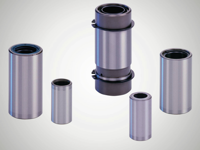
High-precision rotary stroke bearings for backlash-free linear and rotational movements for use in machine and device construction.


Ball-bearing guides for linear and rotational movements without play for use in all technical areas where reliability and precision are required.
The guide diameter finely honed to ISO tolerance IT 3 guarantees the preload of the ball bearing guide in combination with shaft diameter ISO-h3.
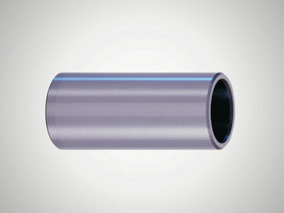
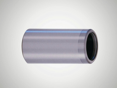
Universal, slim inner bevels on both sides.
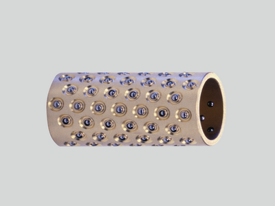
Permanently installed thrust washers on both sides provide a safe travel limit for the ball cage.
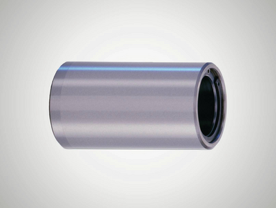
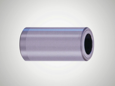
Permanently installed thrust washers on each side and sealing rings prevent impurities from getting into the ball bearing guide.
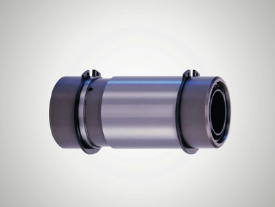
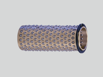
Extra sturdy model with scrapers on both sides which reliably prevent impurities from getting in, even in very dirty environments.
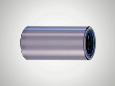
Universal, slim inner bevels on both sides, for use with ball cage from mini series N502.
Permanently installed thrust washers on both sides provide a safe travel limit for the ball cage from mini series N502.
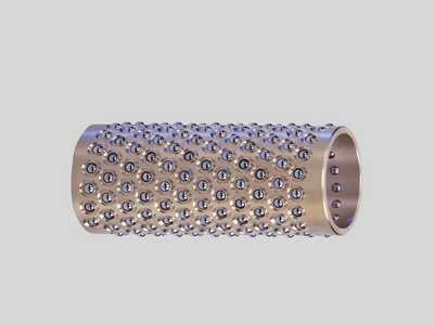
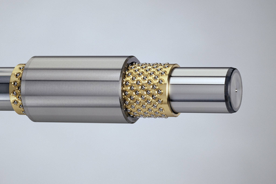
The balls can move easily without getting lost. The balls are arranged in such a way that they run smoothly and ensure a long service life of the ball bearing guide.
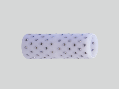
Excellent dry run properties and maximum smoothness, even at high accelerations thanks to the lightweight plastic.
Versatile with balls arranged along a helical line, ideal for linear movements and rotational movements.
Smaller balls used with same shaft diameter compared to type N501. Reduced installation space thanks to guide bushes from the mini series.
High loading capacity thanks to large number of balls, reliable travel limit for the cage thanks to the securing ring.
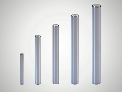
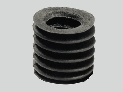
The finely-ground surface is ideal for high precision ball bearing guides, ensuring smooth running and a long service life of the ball bearing guide.
Preload is guaranteed when using with Mahr guide bushes and ball cages.
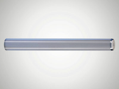
Inner thread on both sides, preload is guaranteed when using with Mahr guide bushes and ball cages.
Broader and more optimized range of uses.
Protect open ball-bearing guides against dirt without compromising smooth movement.
Lubrication for maximum performance and corrosion prevention.
Loading capacity under radial load
The radial load of a rotary stroke bearing is determined by the position of the application point of the radial force PR in relation to the center of the ball contact length e.
The radial force PR can also be the resultant of several forces. Depending on the position of the force application point, the forms of the radial load illustrated in the overview are determined.
The diagram provided in the overview takes into account the deflection of the rotary stroke bearing when a load is applied, which is determined by the elastic deformation of the balls and the surfaces of the guide bush and guide shaft. The axes of the guide bush and guide shaft are assumed to be rigid; the deflection of the shaft must therefore be taken into account, where applicable.
Load of the ball-bearing guide
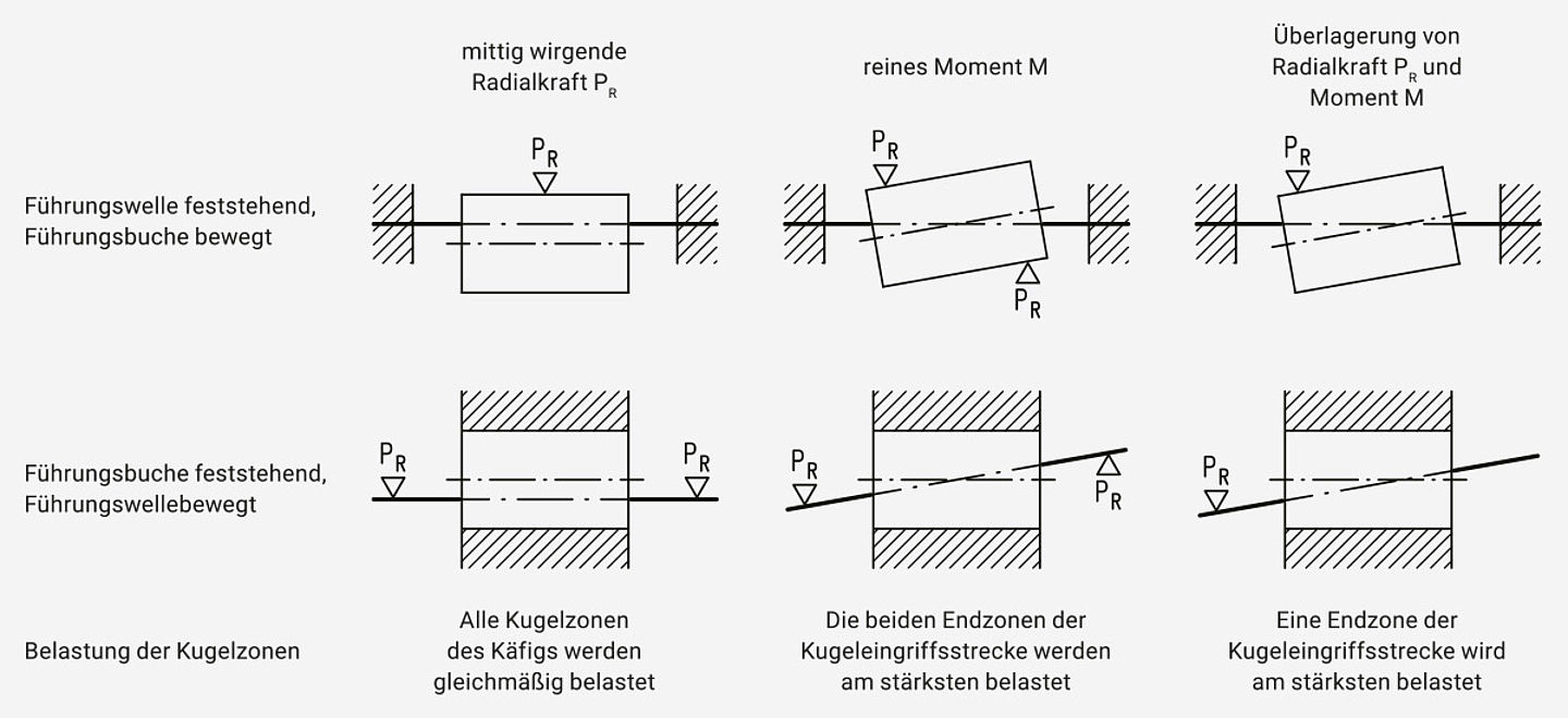
The static radial load can occur in various forms
- The radial load is evenly distributed over the contact length corresponding to a centered radial force PR.
- The radial load is unevenly distributed over the length. In special cases it results in a moment only.
With the different forms of the radial load, the balls in certain sections are charged more than in other sections. The calculation of the loading capacity is based on determining the highest rated radial force P10 of a 10 mm long ball zone. In the following, the correlation between the external load PR or M and the rated radial force P10 are specified for the various forms of the static radial load.
The elastic deformation of the ball zones causes a deflection of the rotary stroke bearing axis. Depending on the load, the elastic deformation of certain ball zones also differs. For a rated radial force P10, the radial deflection of the axis of the most heavily loaded 10 mm ball zone is defined as the specific deflection A10. This can be used to calculate the expected deflection of the shaft at force contact point A.